A reliable zipline braking system is crucial for ensuring both rider safety and operational efficiency. This guide explores the key aspects of choosing and installing the right brake for your course, from calculating arrival speeds to determining correct braking distances. We delve into advanced solutions like self-regulating magnetic brakes, such as the zipSTOP, and self-braking trolleys that provide a smooth, comfortable, and dependable stop for every rider. Learn about technical considerations, including reduction lines and rider orientation, to help you engineer a thrilling zipline experience that is safe, automatic, and easy for your staff to manage.
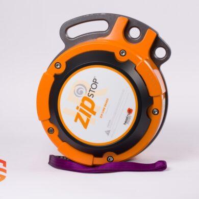
Using self-regulated magnetic braking technology, the zipSTOP slows your zip line riders gradually, comfortably, and reliably.
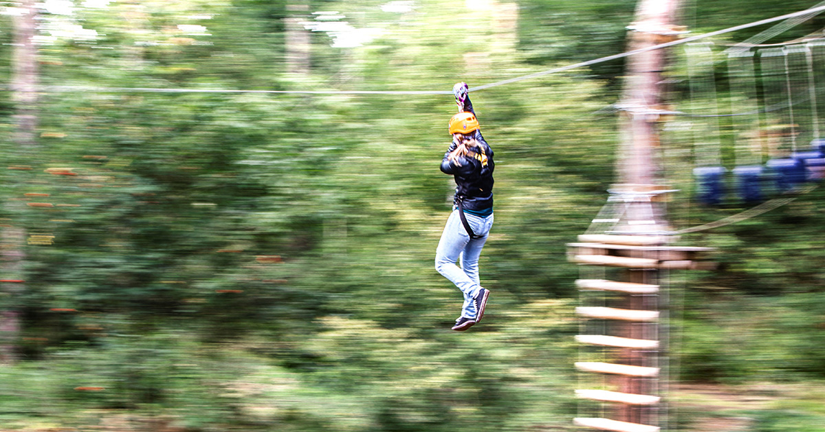
Unlike many other thrill rides, zip lines provide riders a sense of freedom and adventure; riders experience unrestricted movement through the air, wind rushing by, and sights normally reserved for the birds. For riders, the best zip line experience is smooth, easy, and safe, while for staff, it is automatic, fast, and dependable. The zipSTOP zip line brake was designed to give riders the best possible experience while also improving zip line operations.
The zip line must first be built, erected, and properly tested before anyone can ride it. This includes the most important aspect of a zip line ride: braking. Riders frequently have concern about what they must do, how rapidly they will be approaching, and how harsh the stop will be. The zipSTOP, when installed correctly, may make it a simple, automatic, and delightful experience. While we won’t be able to replace the specialized knowledge of zip line builders or engineers in a single post, we will go over the fundamentals of zipSTOP installation to get you started.
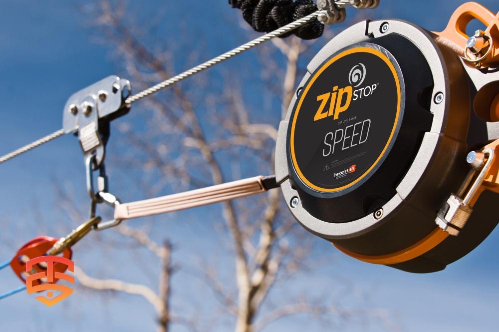
SPEED
Isn’t this the main reason we want to go zip lining in the first place? To soar through the skies, the wind in our hair? Many riders desire higher speeds, yet higher speeds are the enemy of a safe and comfortable stop at the end of the journey. So, how do you deliver a quick ride and then stop your riders gently and comfortably? The zipSTOP offers a variety of possibilities.
To begin with, there are two zipSTOP models to select from. With the use of reduction lines, the zipSTOP can tolerate arrival speeds of up to 24 km/h (15 mph). The zipSTOP IR is a simplified version that can handle speeds of up to 60 km/h (37 mph) without the use of an external reduction line, making installation and maintenance simple.
The arrival speed of a rider is determined by the slope of the zip line, the size and weight of the rider, the wind speed and direction, and the rolling resistance of the rider trolley; each zip line installation will be unique due to the many shifting elements. Calculating the braking lengths for the zipSTOP brake system requires determining the range of rider arrival speed. The braking distances will then enable you to design a platform and retrieval system that gives riders the best possible experience.
Self-braking Zipline trolley with integrated magnetic brake
The key safety difficulties surrounding the regulated and safe braking scenario at the end of high-speed zip wire courses are addressed by our self-braking magnetic zip wire trolley.
The MAG Brake Trolley, which was designed specifically for steep, long, and fast zipline courses, enables for the building of long-distance ziplines without a complex braking area. By eliminating costly and high-maintenance structures, we leave the smallest possible environmental imprint. The MAG Brake zipline Pulley can tolerate a speed drop of up to 35% because to its internal braking mechanism.
All riders will arrive at the same speed, regardless of weight or weather conditions (wind), providing for a safe and controlled braking situation.
-
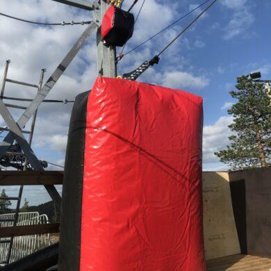 Zipline Airbag | EAD (Emergency Arrest Device)€ 2.500,00 Ex VAT
 -
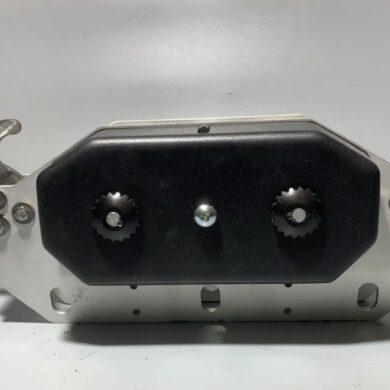
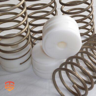 Zipline Spring Brake System | Primary & EAD Braking€ 80,00 Ex VAT
 -
 Self-braking Magnetic Zipline Trolley€ 1.320,00 Ex VAT
BRAKING DISTANCE
You’ll need to know the expected rider weight range for your zip line, the arrival speed range, and the reduction line ratio utilized for the zipSTOP setup to determine the braking distance of a zipSTOP brake system. (We’ll get into the specifics of reduction lines later.) To estimate minimum and maximum braking distances, the zipSTOP handbook includes a helpful spreadsheet and some handy braking distance tables. Of course, these are simply estimations, and actual braking distances should always be determined by unmanned testing.
You can then construct a safe landing area for your participants by calculating these distances. Although the landing area should be large enough to meet the minimum and maximum braking distances, some retrieval for lighter participants should be expected and accounted for. The end of your platform, as well as any other obstacles that riders may come into touch with, should not be inside the maximum braking distance. Beyond the permissible braking distance, a buffer zone is necessary, which should also contain the distance required for an emergency arrest device (EAD) to activate.
The zipSTOP manual also contains braking distance charts that calculate braking distances by relating maximum and minimum arrival speeds to a rider’s weight. The “BDmin Line” is the most important component on these graphs. If riders fall below this line because they are too light or arrive too quickly, they will brake too quickly when they come into touch with the brake trolley. At best, the force would be unpleasant, and at worst, it could cause harm. Always double-check your zip line installation to ensure that riders do not fall below the safety line!
REDUCTION LINES
Reduction lines can be used to adapt the braking system, and we recommend either a 1:1 ratio (for use with the zipSTOP and zipSTOP IR) or a 2:1 ratio (for use with the zipSTOP only, not acceptable for the zipSTOP IR). With a 1:1 ratio, the brake trolley is connected to the zipSTOP by a single redirection line and pulley. This setup is suitable for low speeds because it provides the strongest braking force and shortest braking distance. Because riders will feel the braking forces the most on a 1:1 system, the maximum approach speeds are lower than other setups.
With a 2:1 ratio, an additional pulley is added to the system. This means that for every two feet the brake trolley moves, the zipSTOP braking line will only extend one foot. A 2:1 ratio can be used for zip lines with higher speeds than a 1:1 and will provide a softer braking experience. This ratio will also result in a longer braking distance, though, and should be taken into consideration with your zip line design and platform design.
RIDER ORIENTATION
While the feeling of freely speeding down a zip line is exhilarating, many riders still want to feel some level of control over their experience. The easiest way to do this is to provide them control over their orientation on the way down. This lets them enjoy the view in whichever direction they like, wave to friends on parallel lines, and to keep themselves facing forward when they enter the braking area. This last point is especially important if using impact braking for your zip line.
To solve this problem and more, we created the Specific Zipline Trolleys. These trolleys offers the smoothest ride on the cable, reduces cable wear, and is one of the longest lasting trolleys on the market. With the t-handle added on, the Impact Trolley offers the best rider experience by allowing them to feel in control during the ride and to maintain a safe, forward facing position as they enter the zip line braking zone.
Planning a zipline installation? Need expert advice on zipline design?
Get started Today
The Hardware Behind a Safe, High-Volume Zipline Operation
The products below are used and specified in the techniques described above. Click any item to explore full specifications and request a quote.
How Automatic Reset Braking Keeps High-Volume Ziplines Running
Magnetic eddy-current braking with automatic reset — ideal for high-throughput commercial courses where minimising staff intervention between riders matters.
Why Modular Spring Braking Is the Operator’s Safety Baseline
The modular go-to for operators who need reliable primary and emergency arrest capability. Configurable to your specific rider weight range and arrival speed.
What It Takes to Safely Stop a Rider Arriving at 72 km/h
Engineered for mega-ziplines running at up to 72 kph. The benchmark high-velocity arrest device for operators running the fastest commercial lines.
The Prone Position: How Superman Ziplines Demand Specialist Harnessing
The specialist prone harness for headfirst Superman configurations — redesigned for faster guest harnessing and a more comfortable ride position.
Trolley Longevity vs. Arrival Speed: Why You Don’t Have to Choose
Built to absorb the impact at landing without compromising speed on the line. The choice for courses where trolley longevity and smooth arrival are both non-negotiable.
Heavy Loads, Long Runs: Specifying Trolleys for Serious Commercial Operations
ISC’s large-capacity trolley for high-load commercial operations — built to the bearing quality and durability standards that serious operators expect.
Browse the full Zipline Safety Solutions range →
-
Zipline Spring Brake System | Primary & EAD Braking€ 80,00 Ex VAT
-
Product on sale
 zipSTOP IR Zip Line Brake | Internal Reduction for High-Speed ArrivalPrice range: € 5.742,00 through € 5.894,00 Ex VAT
 -
Product on sale
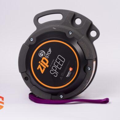 zipSTOP SPEED | High-Velocity Magnetic Braking SystemPrice range: € 6.198,00 through € 6.455,00 Ex VAT